INTRODUCTION
1.1 General
The AFANG field is located in block-00 OML 419, approximately 45 km of the south-eastern coast of Wakanda in approximately 40 meters water depth. The field, initially brought into production in 1997 is owned by the Joint Venture APC/PDP and is operated by APPDPLPC Nigeria Limited (APPDPLPCNL). The OML 419 block is shown in the following figure.
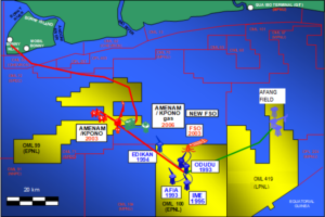
Figure 1-1: Project Scope

Figure 1‑2: AFANG Field Architecture
1.2 Objective
The objective of this document is to confirm adequacy for use, the already selected pipeline concrete weight coating thickness for the 12-inch APC-2 to PDP-1 Crude Export Line.
The line pipe has been coated with 2.7mm 3LPP coating, as well as 30mm concrete weight coating.
1.3 Definitions and Abbreviations
| Definition | |
| Company | APPDPLPC Nigeria Limited |
| Contractor | Global Oceon Nig. LTD |
| Supplier | The Party including its employees, agents, inspectors and other
authorized representatives Contracted by the Company/ Contractor to carry out the Procurement, Construction Installation and Commissioning activities on the Project |
| Shall | Indicates mandatory requirement |
| Should | Indicates preferred recommendation |
Table 1-1: Definitions
1.4 Abbreviations Table 1-2: Abbreviations
| Abbreviation | Definition |
| API | American Petroleum Institute |
| APS | Application Procedure Specification |
| ASME | American Society of Mechanical Engineers |
| CA | Corrosion Allowance |
| CP | Cathodic Protection |
| DNV | Det Norske Veritas |
| DP | Dynamic Positioning |
| 3LPP | 3-Layer Polypropylene |
| FJ | Field Joint |
| FJC | Field-Joint Coating |
| FOS | Factor of Safety |
| HRC | Hardness Rockwell C Scale |
| ID | Inner Diameter |
| LAT | Lowest Astronomical Tide |
| OD | Outside Diameter |
| SG | Specific Gravity |
| SMYS | Specified Minimum Yield Strength |
| WT | Wall Thickness |
1.5.1 Conflict of Information
Where conflict occurs between the requirements of this specification and referenced Codes and Standards, the CONTRACTOR shall notify the COMPANY in writing immediately for resolution. In the absence of such a statement, full compliance with the order of precedence below shall be assumed.
The order of precedence for the documents shall be as follows:
- Nigerian National Regulations Standards
- Project Specification
- International Codes and Standards
Where there are conflicts of interpretation, the principal will review to determine what should apply.
1.5.2 Project Documents
| REF. | DOC No | DOCUMENT TITLE | REV. |
| [R1] | LP-NG-HCD2023-RPT-018 | Wall Thickness Calculation Report | 1 |
| [R2] | LP-NG-HCD2023-RPT-017 | Pipeline Design Basis | 2 |
Table 1-3: Reference and Document
1.5.3 Codes and Standards
| REF. | DOCUMENT NUMBER | DOCUMENT TITLE | REV. |
| [R3] | DNVGL-RP-F109 | On-bottom stability design of submarine pipelines | – |
Table 1-4: Codes and Standards
2.0 SUMMARY AND CONCLUSION
2.1 Summary
The on-bottom stability analysis has been assessed for the 12-inch APC-2 to PDP-1 Crude Export Line and the conservative absolute static stability requirement was considered as per DNVGL-RP F109. The Table 2-1 summarizes the results of the on-bottom stability calculations.
Table 2-1: Absolute Stability Results for Significant Wave Height and Bottom Current Extremes
| Flowline | Load Case | Condition | Concrete Weight Coating Thickness | Calculated Absolute Stability FOS | Allowable FOS | SG
|
Remark | |
| Horizontal | Vertical | |||||||
| 12-inch APC-2 to PDP-1 Crude Export Line | Installation (empty) | 1yr wave, 10yr Current |
30mm |
1.12 | 5.78 |
1 |
1.66 | Satisfies the DNVGL-RP-F109 absolute static stability requirements.
|
| 10yr wave, 1yr Current | 1.44 | 7.55 | ||||||
| Hydrotest | 1yr wave, 10yr Current | 1.43 | 7.19 | 1.96 | ||||
| 10yr wave, 1yr Current | 1.84 | 9.36 | ||||||
| Operation (Corroded Case) | 100yr wave ,10yr current | 1.01 | 4.52 | 1.64 | ||||
| 10yr wave, 100yr current | 1.06 | 4.72 | ||||||
Note:
(1) The specific gravity is the ratio of empty weight in the air to buoyancy and must be greater than 1.15 to satisfy the on-bottom stability requirements.
(2) The factor of safety (FOS) must exceed 1.0 to meet the DNVGL-RP-F109 absolute static stability requirements.
2.2 Conclusion
It is confirmed that the already selected concrete weight coating thickness of 30mm is adequate and satisfies the DNVGL-RP-F109 absolute static on-bottom stability requirement.
3.0 DESIGN BASIS
3.1 Pipeline Design Data
The table below detail parameters used in the calculation spreadsheet attached.
Table 3‑1: Pipeline Characteristics
| Parameters | Units | Values |
| Pipe Steel Outer Diameter (OD) | Inch (mm) | 12.75 (329.3) |
| Pipe Wall thickness | mm | 12.7 |
| Design Pressure | Barg | 144.0 |
| Design Temperature | (0C) | 80 |
| Pipe Grade | – | API 5L X65 |
| SMYS | MPa | 448 |
| SMTS | Mpa | 531 |
| Corrosion Allowance | mm | 3 |
| Steel Poisson Ratio | – | 0.3 |
| Single Joint Length | m | 12.2 |
| Anti-Corrosion Coating Thickness | mm | 2.7 |
| Concrete Coating Thickness | mm | 30 |
| Concrete Coating Poisson Ratio | – | 0.2 |
3.2 Material Densities
The following material densities are used for the pipeline upheaval buckling analysis.
Table 3‑2: Material Properties
| Material | Density (kg/m3) | Youngs Modulus (Mpa) |
| Steel | 7850 | 207000 |
| Anti-corrosion Coating | 1442 | |
| Concrete Weight Coating | 3044 | |
| Seawater | 1030 |
3.3 Content Specific Gravity
The content specific gravity is 0.19.
3.4 Soil Data
The following soil data taken from the Pipeline Design Basis [Ref.R2] are used in the analysis.
Table 3-3: Soil Data
| Parameters | Units | Values |
| Seabed Soil Type | – | Clay |
| Bulk Unit Weight | kN/m3 | 18 |
| Submerged Unit Weight | kN/m3 | – |
| Undrained Shear Strength, Cu | kPa | 4.90 |
3.5 Environmental Data
3.5.1 Water Depth
The following environmental data taken from the Pipeline Design Basis [Ref.R2] are used in the analysis.
Table 3-4: Water Depth
|
Pipeline |
Water Depth (LAT)
(m) |
|
| Minimum | Maximum | |
| 12-inch APC-2 to PDP-1 Crude Export Line | 40.0 | 40.0 |
3.5.2 Wave and Current Data
Wave and current data along the pipeline routes are extracted from the Pipeline Design Basis [Ref.R2] as shown below.
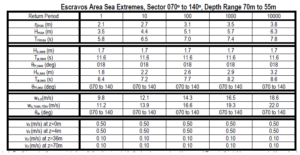
Table 3-5: Significant Wave Height and Associated Current

Table 3-6: Bottom Current Extremes
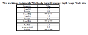
Table 3-7: Wave and Wave Associate with Steady Current Extremes
3.6 Marine Growth
The table below provides growth estimates
Table 3-8: Marine Growth Thickness

4.0 DESIGN METHODOLOGY
4.1 Design Life
The on-bottom stability analysis was based on the absolute static stability criteria set out in DNVGL-RP-F109. In-house spreadsheet has been used for the on-bottom stability analysis.The analysis was performed considering a minimum water depth of 40m which represents the worst-case scenario. The effects of the wave induced velocity along the pipelines are insignificant at this water depth. The stability requirements for the pipeline were determined for installation, hydrotest and operation conditions.
The submerged weight of the pipelines satisfies the On-bottom stability requirements of DNVGL RP F109. A pipeline can be considered to satisfy the absolute static stability requirement if:
- Lateral Stability check
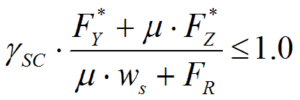
- Vertical Stability check
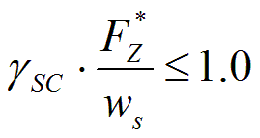
Where;
Ysc : Safety Factor
Ws : Submerged weight of the line (N/m)
µ : Soil friction factor
Fy : Peak Horizontal force (N/m) eq. 3.40 in DNVGL-RP-F109
FZ : Peak vertical force (N/m) eq. 3.41 in DNVGL-RP-F109
Fr : Passive Resistance Force (N/m)
4.2 Assumption
The following assumptions have been made:
- Flat Seabed.
- Minimum water depth has been conservatively considered for the pipeline stability analysis.
- Environmental loading is assumed to act perpendicularly to the pipeline (i.e. θc = 90°).
- Minimum content density has been considered for the operating conditions for the production line as the worst-case scenario.
- The most conservative coefficient of friction (µ=0.2) has been used in this analysis.
- Pipeline penetration and trenching was not considered.
- Marine growth was not considered for hydrotest and installation cases.
- Additional weight due to anodes or any other miscellaneous Pipeline appurtenances are considered as negligible.
4.3 Load Cases
The following load cases had been assessed:
Table 4-1: Load Cases
| Condition | Analysis Water Depth | Sig. Wave Height | Peak Period | Current | Content | Corrosion allowance | Marine Growth |
| Installation | Minimum Water depth along the Route w.r.t LAT | 1year | 1year | 10year | Empty | 3 mm | 0 mm |
| 10year | 10year | 1year | |||||
| Hydrotest | Minimum Water depth along the Route w.r.t LAT | 1year | 1year | 10year | Water | 3 mm | 0 mm |
| 10year | 10year | 1year | |||||
| Operation
(Corroded Case) |
Minimum Water depth along the Route w.r.t LAT | 10year | 10year | 100year | Crude | 2.7 mm | 59 mm |
| 100year | 100year | 10year |
5 RESULT
The result of the concrete weight coating check for 12-inch APC-2 to PDP-1 Crude Export Line is presented in the Table 5-1 below. See calculation spreadsheet in appendix 1.
Table 5-1: Results Summary
| Flowline | Load Case | Condition | Concrete Weight Coating Thickness | Calculated Absolute Stability FOS | Allowable FOS | SG
|
Remark | |
| Horizontal | Vertical | |||||||
| 12-inch APC-2 to PDP-1 Crude Export Line | Installation (empty) | 1yr wave, 10yr Current |
30mm |
1.12 | 5.78 |
1 |
1.66 | Satisfies the DNVGL-RP-F109 absolute static stability requirements.
|
| 10yr wave, 1yr Current | 1.44 | 7.55 | ||||||
| Hydrotest | 1yr wave, 10yr Current | 1.43 | 7.19 | 1.96 | ||||
| 10yr wave, 1yr Current | 1.84 | 9.36 | ||||||
| Operation (Corroded Case) | 100yr wave ,10yr current | 1.01 | 4.52 | 1.64 | ||||
